
The information on this page is taken from the GPON standard and information from the major vendors of GPON equipment, each individual item containing a verifiable citation in the standard. Feel free to cite this page as: GPON G.984 Series, Hack GPON. Available at: https://hack-gpon.org/g_984_series/.
| G.984.1 | G.984.2 | G.984.3 | G.984.4 | G.988 (ex G.Imp984.4) |
|---|---|---|---|---|
| General Characteristics | Physical Media Dependant Layer | Transmission Convergence Layer | ONT Management & Control Interface | OMCI Implementer's Guide |
| Architecture | Bit Rate/coding | GTC Protocol | Reference model | |
| Distance/Reach | Wavelength | GTC Framing | OMCI requirement | |
| Split Ratio | Optical element specs and operation | ONU Activation | MIBs | |
| Protection | Link budget (amendment) | Security / FEC | OMCC | |
| Alarms / Monitoring | ||||
| OMCI |
Other recommendations of the series are G.984.5 (enhancement band, wavelengths reserved for the coexistence with the next generation PONs), G.984.6 (reach extension) and G.984.7 (long reach).
The ITU-T PON family
GPON is the second generation of the ITU-T PONs. The following generations reuse most of its concepts (ONU-ID, Alloc-ID, T-CONT, GEM ports, PLOAM, OMCI), with a different physical layer and a different TC layer (XGTC, XGEM)[1],[2]:
| Recommendation | Name | Year | Downstream | Upstream | Downstream wavelength | Upstream wavelength |
|---|---|---|---|---|---|---|
| G.983 | BPON | 1998 | 622 Mb/s | 155 Mb/s | 1490 nm | 1310 nm |
| G.984 | GPON | 2003 | 2.48832 Gb/s | 1.24416 Gb/s | 1480 - 1500 nm | 1260 - 1360 nm |
| G.987 | XG-PON | 2010 | 9.95328 Gb/s | 2.48832 Gb/s | 1575 - 1580 nm | 1260 - 1280 nm |
| G.9807.1 | XGS-PON | 2016 | 9.95328 Gb/s | 9.95328 Gb/s (or 2.48832 Gb/s) | 1575 - 1580 nm | 1260 - 1280 nm |
| G.989 | NG-PON2 | 2015 | 4-8 x 9.95328 Gb/s (TWDM) | 4-8 x 2.48832/9.95328 Gb/s | 1596 - 1603 nm | 1524 - 1544 nm |
| G.9804 | 50G-PON (HSP) | 2021 | 49.7664 Gb/s | 12.44, 24.88 or 49.77 Gb/s | 1340 - 1344 nm | several options, see G.9804.3 |
Since the wavelengths are different, GPON and XGS-PON can share the same ODN: the OLT uses either two ports combined with an external WDM filter (the coexistence element, WDM1r, defined in G.984.5), or a single combo PON port with both transceivers and the WDM filter integrated in the same optic. Each ONU only sees its own wavelengths, so a GPON ONU keeps working when XGS-PON is added to the same fiber.
The IEEE alternative to the ITU-T PONs is EPON, see EPON IEEE 802.3ah/av Series.
General Concepts[3]
- Bitrate: 1.2 Gbps Upstream; 2.4 Gbps Downstream.
- Physical Reach: Max physical distance between OLT and ONT.
- Differential Fiber Distance: Distance between closest and farthest ONT from OLT (max = 20km)
Basic Performance Parameters[4]
| Upstream (Rate - Gbps) | Downstream (Rate - Gbps) |
|---|---|
| 0.15552 | 1.24416 |
| 0.62208 | 1.24416 |
| 1.24416 | 1.24416 |
| 0.15552 | 2.48832 |
| 0.62208 | 2.48832 |
| 1.24416 | 2.48832 |
| 2.48832 | 2.48832 |
1.24416 Gbps up, 2.48832 Gbps down is the most supported speed combination at current time.
Physical layer (G.984.2)[5]
| Parameter | Value |
|---|---|
| Downstream wavelength | 1480 - 1500 nm (1490 nm) |
| Upstream wavelength | 1260 - 1360 nm (1310 nm) |
| Video overlay | 1550 - 1560 nm (RF video, enhancement band defined in G.984.5) |
| Line coding | NRZ, scrambled with the polynomial x7 + x6 + 1 (no 8b/10b, unlike EPON) |
| Downstream transmission | continuous, broadcast to all the ONUs |
| Upstream transmission | burst mode TDMA, the ONU laser is switched on only in its allocated time slots |
| Fiber | single-mode, ITU-T G.652 |
| Physical reach | 20 km (10 km for some low budget optics) |
| Logical reach | 60 km, max differential distance 20 km |
| Split ratio | up to 1:64 (1:128 at the TC layer) |
The power budget is described by the optical classes. The Channel Insertion Loss (ChIL) is the attenuation of the ODN (fiber, splitters, connectors and splices) that the optics must support:
| Class | Min ChIL | Max ChIL | Notes |
|---|---|---|---|
| A | 5 dB | 20 dB | |
| B | 10 dB | 25 dB | |
| B+ | 13 dB | 28 dB | the most common class for the ONUs and the OLTs |
| C | 15 dB | 30 dB | |
| C+ | 17 dB | 32 dB | used for longer reach or higher split ratios (e.g. 1:128) |
For example a 1:32 splitter introduces about 17 dB of loss, plus about 0.35 dB/km of fiber at 1310 nm: with a class B+ optic a 1:32 split on 20 km of fiber is within the budget.
GPON Terminology
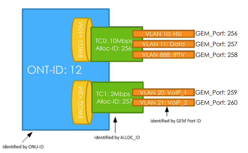
ONU Identifier (ONU-ID)[3:1]
- 8 bit identifier (0~255)
- 0 .. 253 Assignable
- 254 Reserved
- 255 Broadcast/unassigned
- The OLT assigns an id to any ONU during the ONU's activation using the PLOAM channel.
- ONU-ID is unique across the PON and remains valid until the ONU is powered off, deactivated by the OLT or moves itself into an inactive state.
Allocation Identifier (Alloc-ID)[3:2]
- Alloc-ID is a 12-bit identifier (0 .. 4095) that the OLT assigns to an ONU's traffic-bearing entity.
- 0 .. 253 Default
- 254 Broadcast
- 255 Unassigned
- 256 .. 4095 Assignable
- A Traffic-bearing entity can be represented either by a T-CONT or by the upstream OMCC.
Transmission Containers (T-CONT)[3:3],[6]
A Transmission Container (T-CONT) is an ONU object representing a group of logical connections that appear as a single entity for the purpose of upstream bandwidth assignment on the PON.
- Bandwidth assignment and QoS control are performed in every T-CONT by fixed and dynamic methods.
- There are 5 types of T-CONT Traffic Descriptors:
- Type 1: fixed bandwidth;
- Type 2 and Type 3: guaranteed bandwidth;
- Type 4: best-effort;
- Type 5: mixed type, involving all bandwidth types and bearing all services
| Type 1 | Type 2 | Type 3 | Type 4 | Type 5 |
|---|---|---|---|---|
| SIR | SIR | |||
| AIR | AIR | AIR | ||
| PIR = SIR | PIR = AIR | PIR > AIR | PIR | PIR >= SIR + AIR |
- For TR-156 and TR-167, each T-CONT represents a traffic class
- Each ONU is assigned at least one Alloc-ID which is equal to that ONU's ONU-ID and may be assigned additional Alloc-IDs per the OLT's discretion.
- Typically have 4 T-CONTs, supporting 4 traffic classes, plus an extra one for OMCI
- The default Alloc-ID is used to carry the upstream PLOAM and OMCC traffic and may carry user data traffic.
- The OLT schedules upstream traffic across all ONUs according to the priority and weight assigned to each T-CONT, and their buffer occupancy. Other bandwidth assignment mechanisms are available, for example fixed bandwidth, assured bandwidth, and nonassured bandwidth[6:1].
Dynamic Bandwidth Allocation (DBA)
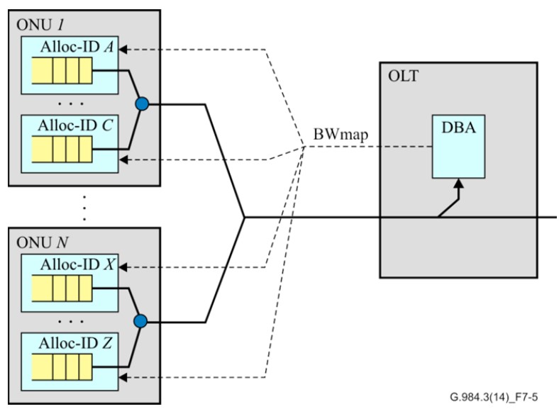
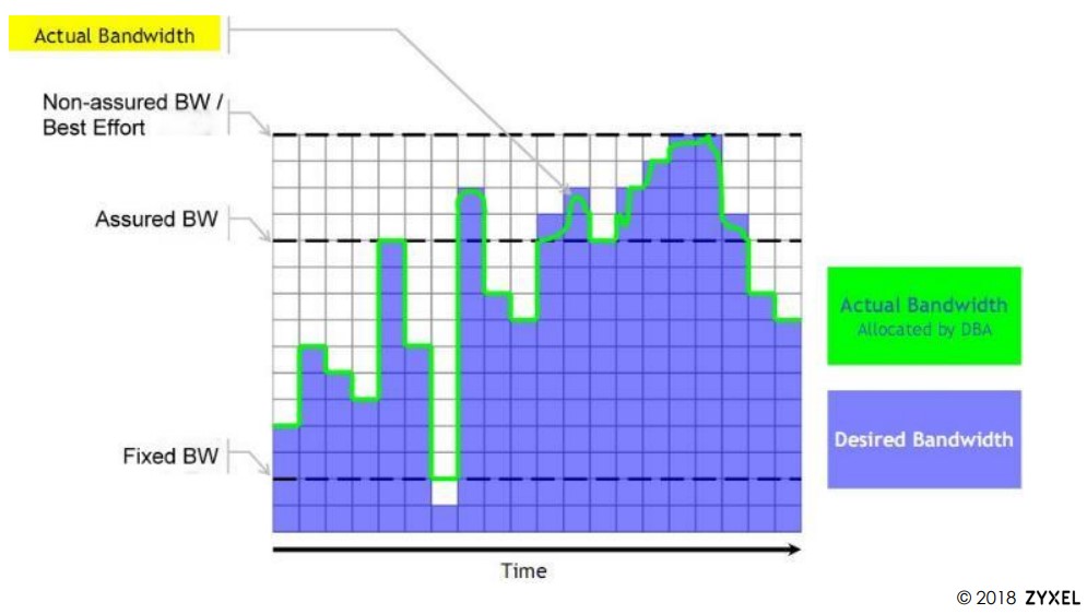
Dynamic Bandwidth Allocation (DBA) is a technique by which traffic bandwidth in a shared telecommunications medium can be allocated on demand and fairly between different users of that bandwidth. It is performed on the upstream traffic[3:4].
With DBA, the OLT assesses the bandwidth needs of the ONUs in real time and allocates upstream PON capacity accordingly[6:2].
DBA basic model supports[3:5]:
- Fixed bandwidth (highest priority)
- Assured bandwidth
- Non-assured bandwidth
- Best-effort bandwidth (lowest priority)
GPON transmission basics[4:1]
Key Terms:
- Physical layer overhead upstream (PLOu) - Upstream physical layer overhead.
- Physical layer OAM upstream (PLOAMu) - PLOAM messages of upstream data. Think of this as a message-based operation and management channel between the OLT and ONU/ONTs.
- Power level sequence upstream (PLSu) - Upstream power level sequence
- Dynamic bandwidth report upstream (DBRu) - Upstream dynamic bandwidth report
- Payload - User data
- PCBd - Physical Control Block downstream
- OMCC - Optical Network Unit Management and Control Channel
- OMCI - Optical Network Unit Management and Control Interface
GPON Encapsulation
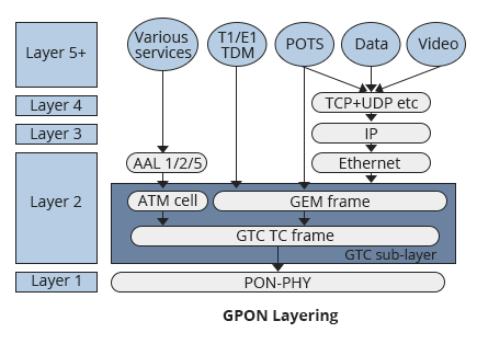
GPON uses two layers of encapsulation:
- TDM and Ethernet frames are wrapped into GTC Encapsulation Method (GEM) frames, which have a GFP-like format (derived from Generic Frame Procedure ITU G.7401). The main purpose of the GEM frame is to provide a frame-oriented service, as an alternative to ATM, in order to efficiently accommodate Ethernet and TDM frames. With GEM, all traffic is mapped across the GPON network using a variant of SONET/SDH GFP. GEM natively supports transportation of voice, video, and data without an added ATM or IP encapsulation layer[7],[8].
- ATM and GEM frames are both encapsulated into GTC frames that are finally transported over the PON[7:1],[8:1]. The ATM transport was defined in the first version of G.984.3, but it has been removed in the 2008 revision and it is not used by the deployed equipment.
ITU-T G.984 defines GEM as the only data transport scheme for GPON. Bandwidth allocation in GPON grants individual transmission opportunities to the ONU's traffic-bearing entities on the timescale of a single GTC frame[3:6].
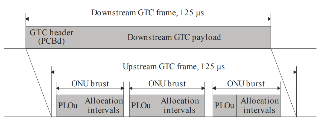
As shown in the image, the difference between a downstream and upstream frame.
Downstream[3:7],[6:3],[4:2]
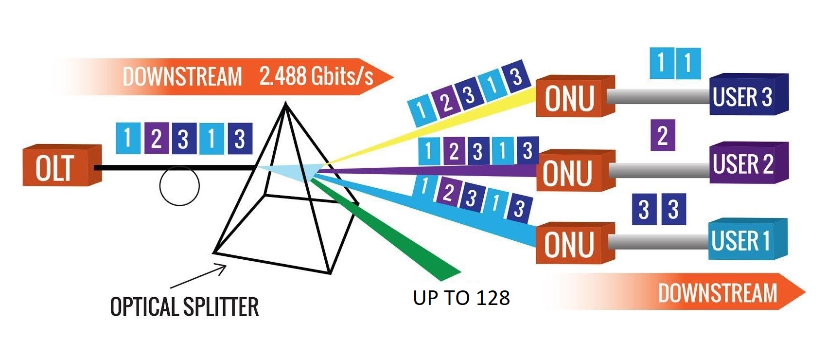
A downstream GPON frame has a fixed length of 125 μs and is 38880 bytes long which corresponds to the downstream data rate of 2.48832 Gbps, comprised of two components: physical control block downstream (PCBd) and payload.
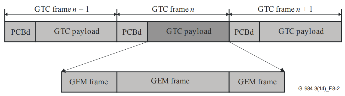
The PCBd length range depends on the number of allocation structures per frame.
The OLT broadcasts PCBd to all ONU/ONTs. The ONU/ONTs receive the PCBd and performs operations based on the information received. GPON use Broadcast downstream data transmission with AES (Advanced Encryption Standard) to ensure secure delivery to destination:
- Traffic multiplexing is centralized.
- GEM Port-ID is the key to identify the GEM frames that belong to different downstream logical connections.
- Only frames with the appropriate Port-IDs are allowed through to the GEM client function.
- Each ONU filters the downstream GEM frame based on their GEM Port-ID and processes only the GEM frames that belong to that ONU.
PCBd consists of the GTC header and BWmap:
- GTC Header - Used for frame delimitation, synchronization, and forward error correction (FEC).
- BWmap - Field notifies every ONU of upstream bandwidth allocation. Specifies the start and end upstream time slots for the T-CONTs of each ONU. This ensures that all ONUs send data based on the time slots specified by the OLT to prevent data conflict.
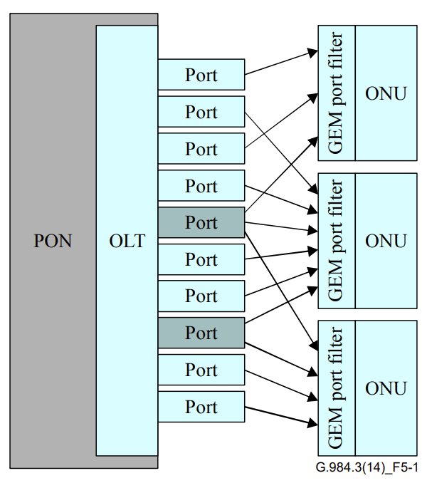
- The OLT sends Ethernet frames from Uplink ports to the GPON service processing module based on configured rules to the PON ports.
- The GPON service processing module then encapsulates the Ethernet frames into GEM port data packets for downstream transmission.
- GPON transmission convergence (GTC) frames that contain GEM PDUs are broadcast to all ONT/ONUs connected to the GPON port.
- The ONT/ONU filters the received data based on the GEM port ID contained in the GEM PDU header and only retains data significant to the GEM ports on this ONT/ONU.
- The ONT decapsulates the data and sends the Ethernet frames to the end users via service ports.
Upstream[3:8],[6:4],[4:3]
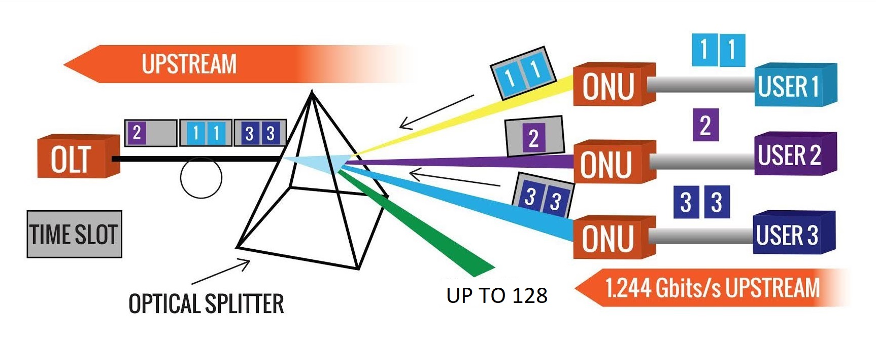
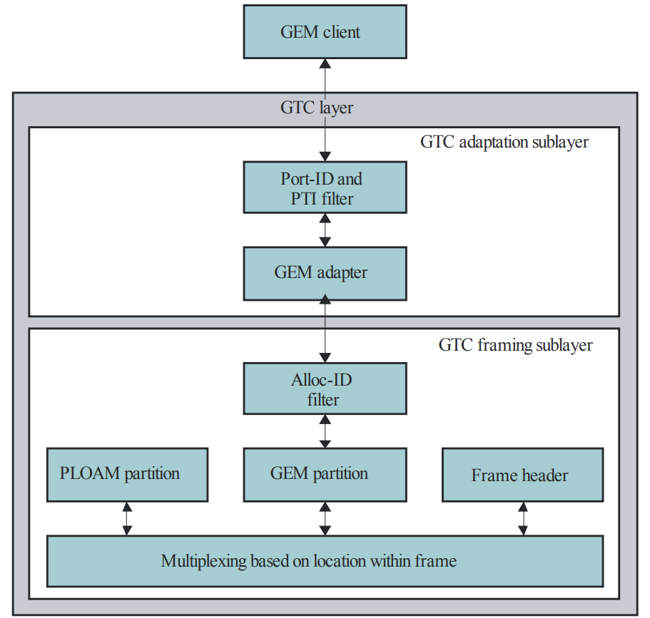
In the Upstream channel, GEM traffic is carried over one or more T-CONTs. The OLT receives the transmission associated with the T-CONT and the frames are forwarded to the GEM TC adapter and then the GEM client.
- Use Time Division Multiple Access (TDMA) for upstream data transmission w/o AES encryption.
- Distance between the OLT and ONT/ONU is measured (Ranging):
- The OLT starts the process on an ONU when the ONU first registers with the OLT and obtains round trip delay (RTD) of the ONU. Based on the RTD, other key components are identified:
- Calculation of the physical reach of that specific ONU, as this OLT requires a proper equalization delay (EqD) for each ONU based on physical reach.
- RTC and EqD synchronize data frames sent by all ONUs.
- Time slots are allocated based on distance. In order to prevent data conflict (collisions), the OLT must be able to precisely measure the distance between itself and each ONU to provide a proper time slot to facilitate data upstream. This allows the ONUs to send data at specified time slots, to prevent issues upstream. This process is achieved through a technique called ranging.
- The ONT/ONU sends traffic upstream based on the granted time slot.
- Distance between the OLT and ONT/ONU is measured (Ranging):
- Dynamic Bandwidth Allocation (DBA) enables the OLT to monitor in real-time, congestion, bandwidth usage, and configuration.
- Traffic multiplexing is distributed.
- The OLT grants upstream bandwidth allocation.
- The ONU traffic-bearing entities are identified by their Allocations IDs.
- Alloc-IDs are multiplexed in time as specified by the bandwidth-map (provided by the OLT in the downstream frame).
- Within its bandwidth allocation, the ONU uses the GEM Port-ID as key to identify upstream GEM frames.
- Each upstream frame contains the content carried by one or more T-CONTs.
- All ONUs connected to a GPON port share the upstream bandwidth.
- All ONUs send their data upstream at their own time slots based on bandwidth map (BWmap) requirements.
- Each ONU reports the status of data to be sent to the OLT by use of upstream frames. OLT uses DBA to allocate upstream time slots to ONUs and sends updates in each frame.
- Burst Technology: Upstream packet flow is achieved via bursts, with each ONU/ONT responsible for data transmission within its allocated time slots. When an ONU/ONT is not within its time slot, the device disables transmission of its optical transceiver to prevent other ONU/ONT impact.
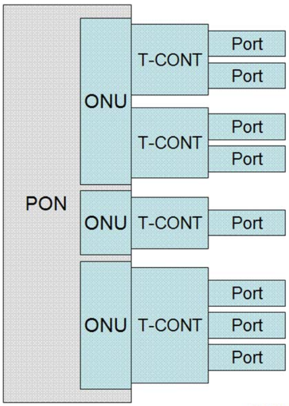
- ONT/ONUs send Ethernet frames to GEM ports based on configured rules that map service ports and GEM ports.
- GEM ports encapsulate the Ethernet frames into GEM PDUs and add these PDUs to T-CONT queues based on rules that map GEM ports and T-CONT queues.
- T-CONT queues use time slots based on DBA, then transmit upstream GEM PDUs to the OLT.
- OLT decapsulates the GEM PDU, the original Ethernet frame is now seen.
- OLT sends the Ethernet frames from a specified uplink port based on rules that map service ports and uplink ports.
Protocol stack for the C/M-plane[9]
The control and management plane in the GTC system consists of three parts: embedded OAM, PLOAM and OMCI. The embedded OAM and PLOAM channels manage the functions of the PMD and the GTC layers. The OMCI provides a uniform system for managing higher (service-defining) layers.
Configuration Methods[3:9]
Several methods are available for the installation and activation of the ONU.
- Method A: Match serial number and password.
- Method C: Match PLOAM password or serial number.
- Method C-autolock: Match serial number.
- Method D: Volatile auto provision by template.
- Method E: Non-volatile auto provision by template.
If the ONU is not legal, the ONU registration activation will fail, see GPON Auth for the ONU States.
PLOAM messages[9:1]
PLOAM (Physical Layer OAM) is the message channel between the OLT and the ONU used for the activation, the ranging, the authentication and the encryption keys. The downstream PLOAM messages are carried in the PCBd of every frame, the upstream ones in the PLOAMu field of the burst. The most important messages are:
| Message | Direction | Usage |
|---|---|---|
Upstream_Overhead | OLT → ONU | preamble, delimiter and pre-assigned delay to use in the upstream bursts (O2) |
Serial_Number_ONU | ONU → OLT | the ONU sends its serial number (vendor ID + vendor specific serial number) (O3) |
Assign_ONU-ID | OLT → ONU | assigns the ONU-ID to the serial number (O3) |
Ranging_Time | OLT → ONU | equalization delay computed with the ranging (O4) |
Request_Password | OLT → ONU | requests the password of the ONU |
Password | ONU → OLT | the PLOAM password (10 bytes) of the ONU |
Assign_Alloc-ID | OLT → ONU | assigns the Alloc-IDs of the T-CONTs |
Encrypted_Port-ID | OLT → ONU | enables or disables the encryption of a GEM port |
Request_Key | OLT → ONU | requests a new encryption key |
Encryption_Key | ONU → OLT | the new encryption key, sent in two fragments |
Key_Switching_Time | OLT → ONU | the frame from which the new key is used |
Deactivate_ONU-ID | OLT → ONU | deactivates the ONU, which goes back to O1 |
Disable_Serial_Number | OLT → ONU | disables (O7) or enables again the ONU with the given serial number |
Dying_Gasp | ONU → OLT | the ONU is losing the power |
The serial number is the identifier of the ONU and the password is the only credential checked at the PLOAM level: this is why on Hack GPON the GPON serial number and the PLOAM password are the first parameters to change when an ONU is replaced. Other credentials, such as the LOID, are checked later through OMCI.
Security
The security model is very different between GPON and the next generation ITU-T PONs (XG-PON, XGS-PON, NG-PON2), which redesigned it from scratch.
GPON (G.984.3)[9:2]
- Encryption: AES-128 in counter mode, downstream only. The upstream is not encrypted, since an ONU cannot receive the upstream of the other ONUs (the splitter only sends it to the OLT). The encryption is enabled per GEM port (unicast GEM ports only, the multicast ones are not encrypted).
- Key exchange: the key is generated by the ONU and sent in clear to the OLT in the upstream PLOAM
Encryption_Keymessage, requested byRequest_Keyand activated withKey_Switching_Time. The security relies on the fact that the upstream cannot be received by the other ONUs. - Authentication: only the serial number and the PLOAM password, both sent in clear upstream, and optionally the LOID through OMCI. There is no authentication of the OLT and no integrity check of the PLOAM and OMCI messages.
XG-PON, XGS-PON and NG-PON2 (G.987.3, G.9807.1, G.989.3)[1:1],[2:1]
- Encryption: AES-128 in counter mode in both directions: the downstream unicast and broadcast/multicast GEM ports and, optionally, the upstream unicast GEM ports.
- Key exchange: the data encryption keys are generated by the ONU and sent to the OLT encrypted with the KEK (Key Encryption Key), using the PLOAM messages
Key_ControlandKey_Report; the broadcast keys are distributed through OMCI. - Integrity: the PLOAM and OMCI messages have a MIC (Message Integrity Check), computed with the integrity keys derived from the master session key.
- Authentication: the serial number and the Registration ID (36 bytes, it replaces the 10 bytes GPON password) in the
RegistrationPLOAM message. Optionally the ONU and the OLT can authenticate each other (mutual authentication) through OMCI (ME Enhanced security control) or IEEE 802.1X, which produces the master session key. Without the mutual authentication, the keys are derived from default values defined by the recommendation, so the encryption and the integrity check still work but the ONU and the OLT are not authenticated.
| Feature | GPON | XG-PON / XGS-PON |
|---|---|---|
| Downstream encryption | AES-128 CTR, unicast GEM ports | AES-128 CTR, unicast and broadcast/multicast GEM ports |
| Upstream encryption | No | AES-128 CTR, optional, unicast GEM ports |
| Key transport | in clear, PLOAM upstream | encrypted with the KEK, PLOAM Key_Report |
| Message integrity | No | MIC on PLOAM and OMCI |
| ONU credential | PLOAM password (10 bytes) | Registration ID (36 bytes) |
| Mutual authentication | No | Optional (OMCI or IEEE 802.1X) |
FEC (Forward Error Correction)
| Technology | Downstream FEC | Upstream FEC |
|---|---|---|
| GPON | RS(255,239), optional | RS(255,239), optional |
| XG-PON | RS(248,216), mandatory | RS(248,232), optional |
| XGS-PON | RS(248,216), mandatory | RS(248,216), optional |
In GPON the FEC is optional and it is enabled by the OLT independently for each direction: the downstream FEC is signalled in the GTC header (the FEC indication bit of the PCBd), the upstream FEC is requested by the OLT for each allocation with the Use FEC flag of the BWmap. The RS(255,239) code adds 16 parity bytes every 239 data bytes (about 7% of overhead) and corrects up to 8 bytes per codeword, which gives about 3 dB of additional power budget[9:3].
Protocol Stacks[4:4],[8:2]
GPON has its own layer 2 (the GTC sublayer) below Ethernet: the services (data, POTS, video, TDM) are carried over Ethernet/IP or directly over GEM, and everything is framed by the GTC layer over the PON physical layer.
Ethernet over GEM[9:4]
The Ethernet frames are carried directly in the GEM frame payload. The preamble and start frame delimiter (SFD) bytes are discarded prior to GEM encapsulation. Each Ethernet frame shall be mapped to a single GEM frame (as shown in Figure) or multiple GEM frames, in which case the fragmentation rules apply.
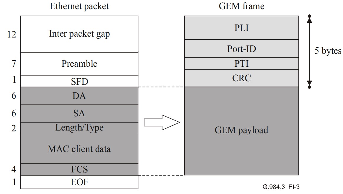
Resolves Ethernet frames and directly maps the data of Ethernet frames into the GEM payload. GEM frames automatically encapsulate header information.
1:1 alignment between an Ethernet Frame and GEM Frame.
OMCI[4:5]
- ONU Management and Control Interface (OMCI) messages are used to discover ONT/ONUs for management and control.
- These specialized messages are sent over dedicated GEM ports established between an OLT and an ONT/ONU.
- The OMCI protocol allows an OLT to:
- Establish and release connections with the ONT.
- Manage the UNIs on the ONT.
- Request configuration information and performance statistics.
- Autonomously alert events, such as a link failure.
- Key Points:
- Protocol runs over a GEM connection between the OLT and ONT.
- GEM connection is established while the ONT initializes.
- Protocol operation is asynchronous - OLT controller functions as a primary, ONT controller as secondary.
Management Information Base (MIB) and Management entities (ME's)[10]
MIBs (Management Information Base) formed by Management Entities (MEs) are used to fully describe the ONU configuration, status and several other actions.
OMCI constitutes the protocol which supports the set of actions performed over an ONU to create, delete and more on those MEs
- A Managed Entity (ME) is composed of attributes, actions and notifications defining its characteristics.
- Managed Entity (ME Class Value)
- Purpose of the entity
- Autonomously instantiated by the ONU or explicitly created by the OLT
- Relationship(s) with other managed entities
- Attributes: Attribute Definition
- ME id: provides a unique number for each instance of this managed entity.
- List of attributes: Attribute Number within ME determined by the order in which attributes are listed
- Actions: operations that may be performed on the entity (Create/Get/Set/Test, etc.)
- Notifications (Alarm, AVC, TCA, Test Result)
- There can be multiple instances of any Managed Entity: each instance has the same attributes, actions and notifications even though the values of the attributes may be different from one another.
VEIP and PPTP[11],[12]
According to the application, ONU can be divided into six types, namely SFU (Single Family Unit) ONU, HGU (Home Gateway Unit) ONU, MDU (Multi-Dwelling Unit) ONU, SBU (Single Business Unit) ONU, MTU (Multi-Tenant Unit) ONU and CBU (Cellular Backhaul Unit) ONU. However, only SFU (Single Family Unit) ONU and HGU (Home Gateway Unit) ONU are used by the end-users in practical applications.
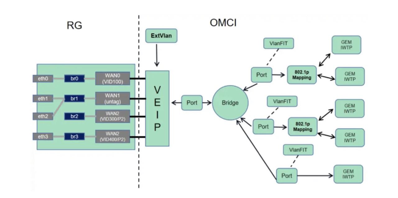
HGU ONU takes the Virtual Ethernet Interface Point (VEIP) as an OMCI administrative domain and a non-OMCI administrative domain (like TR-069). At the switchover point of the data plane, the ME can be managed only through the OMCI and is visible to the non-OMCI management domain, but not manageable. Similarly, all UNI-side modules under the VEIP are invisible to and cannot be managed by the OMCI. They are visible and manageable only to the non-OMCI management domain. In addition, each ONU should have only one VEIP.
When the ONU uploads MIBs, the ONU reports only the mandatory MEs and supported optional MEs. It does not report the MEs related to LOID authentication, performance monitoring and T-CONT MEs of the OMCC channel.
The ONU should be used according to the device type and report either VEIP or PPTP during MIB upload. The SFU only uses and reports PPTP. VEIP should not be used. HGUs can only use and report VEIPs. PPTP should not be used. The OLT determines the ONU type based on the ONU Type attribute in ME:ONU Capability. Only one VEIP is allowed in each HGU. ONUs will report VEIP or PPTP (Physical Path Termination Point) when MIB is uploaded according to the type of the device, while HGUs can only use and report VEIP rather than PPTP. The OLT will judge the type of each ONU device according to the ONU type attribute in ONU capability.
SFU ONUs only support the OMCI management domain. PPTP is what SFU uses and reports, while VEIP is not available. The processing mode of OMCI configured data flow is different from that of RG flow. For OMCI data flow, there is a one-to-one mapping between the GEM port on the WAN side and the UNI port on the LAN side. All data packets can pass through without MAC address learning or forwarding. Wireless interfaces are not allowed in OMCI.
SFU ONUs are designed for a single family unit with broadband access terminal function without a more complex home gateway function from the perspective of application and ONU capacity. SFU ONUs, mainly used in FTTH scenarios, typically have 1 or 4 Ethernet interfaces and are available for Ethernet / IP services, optional VoIP services (built-in IAD), or CATV services.
SFU ONUs work under bridging mode (layer 2 of ISO model), support multiple VLAN functions, and their Ethernet port can be configured and managed by the OLT through OMCI / OAM. Combined with a home gateway, SFU ONUs are good at providing strong service capability.
G.987.3: 10-Gigabit-capable passive optical networks (XG-PON): Transmission convergence (TC) layer specification https://www.itu.int/rec/T-REC-G.987.3 ↩︎ ↩︎
G.9807.1: 10-Gigabit-capable symmetric passive optical network (XGS-PON) https://www.itu.int/rec/T-REC-G.9807.1 ↩︎ ↩︎
GPON E2E Fundamentals, Zyxel 2018 ↩︎ ↩︎ ↩︎ ↩︎ ↩︎ ↩︎ ↩︎ ↩︎ ↩︎ ↩︎
Understand GPON Technology https://www.cisco.com/c/en/us/support/docs/switches/catalyst-pon-series/216230-understand-gpon-technology.html ↩︎ ↩︎ ↩︎ ↩︎ ↩︎ ↩︎
G.984.2: Gigabit-capable passive optical networks (GPON): Physical Media Dependent (PMD) layer specification https://www.itu.int/rec/T-REC-G.984.2 ↩︎
GPON in FTTx Broadband Deployments, Broadband Forum 2010 https://www.broadband-forum.org/download/MR-246.pdf ↩︎ ↩︎ ↩︎ ↩︎ ↩︎
HTFuture: EPON vs GPON Standard https://medium.com/@ivyhtfuture/epon-vs-gpon-standard-b8ec20c55bb3 ↩︎ ↩︎
Comparison of EPON and GPON https://community.fs.com/blog/comparison-of-epon-and-gpon.html ↩︎ ↩︎ ↩︎
G.984.3: Gigabit-capable passive optical networks (GPON): Transmission convergence layer specification https://www.itu.int/rec/T-REC-G.984.3 ↩︎ ↩︎ ↩︎ ↩︎ ↩︎
Gpon: Tecnology, ARSAT ↩︎
VEIP knowledge https://forum.huawei.com/enterprise/en/veip-knowledge/thread/771975-100181 ↩︎
Differences between HGU ONU and SFU ONU https://cdatatec.com/differences-hgu-onu-sfu-onu/ ↩︎